Replacing the belt transmission on your Yardbeast 2090 Wood Chipper Shredder.
- Apr 26, 2023
- 3 min read
Updated: Jun 28, 2023
In this tutorial, we will cover how to make a complete transmission swap on your chipper. The model utilized here is the 2090 wood chipper shredder, but the idea is pretty much the same on all of our chippers. This tutorial serves well if you need to change the clutch, the pulleys, or the belts on any of our residential-grade chippers.
Step 1.
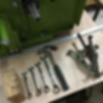
First off, tools are needed. We will use:
7/16" | 1/2" | 9/16" | 3/4" hex wrench (one of each).
1- Pulley extractor (optional, but handy).
1- Long straight edge (make it at least one foot long).
1- hammer or rubber mullet
1- a piece of hardwood
Step 2.
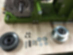
What you'll need
1- Pulley with 1" tapered hub with 1/4" key
1- Clutch with key.
1- Hex Bolt 3/8" x 1-1/2" NF grade 5. (black)
1- Hex Bolt 3/8" x 1" NC grade 5
2- 3/8" Flat washers
2- 5/16" Flat washers
4- 1/4" x 1" hex bolts grade 5 -black colored (2 are added in case you need to realign pulley)

Step 3.
Now grab the 3/8 x 1-1/2" Bolt and assemble with a 5/16" flat washer first, and then with a 3/8" flat washer, and apply a dab of thread locker to secure the fastener.

Step 4.
Screw the setup in place. This step is very important to achieve a correct wood chipper belt transmission swap.
Step 5.
Tighten with one hand pulling gently on the starting recoil rope and the other with the 9/16" hex wrench in a clockwise manner.

Step 6.
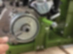
Pulley Assembly
Now onto the rotor shaft. Insert the tapered hub into the pulley. Align the hub unthreaded holes with the pulley holes. Screw in the two bolts and tighten them by hand. Do not tighten with tools yet.

Step 7.
Slide the pulley and hub on the rotor shaft. Align keyways and insert key. If needed, hit the key mildly with a hammer. At this point, the pulley should still be able to slide by hand, if not we can use a hammer and a piece of wood to correct the position. Align by eye with grooves on the clutch.

Step 8.
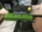
Belt assembly
Insert the belts. First, make sure that the engine is pushed all the way closest to the rotor shaft. Insert the belts by placing the belt on the clutch grooves first. Then finish off by rotating the pulley and the belt will slip into position by itself. Make sure that your fingers don't get pinched between the belts and grooves!
Step 9.
Pull the engine away from the rotor by adjusting the engine bolt in a clockwise manner. Tighten until the belt looks firm. We will apply the required belt tension in the next steps.

Step 10.
You will notice that when the engine is being pulled away, it will veer off because of the belt tension that is being applied. To correct this, adjust the side bolt in a clockwise manner until the engine is straight.

Step 11.
To make sure the engine is straight, measure the length between the engine base face and the face of the chipper base. On each side. The variation allowed to our specs is 1mm or 0.04".
Step 12.
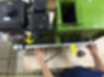
Now place a straight edge that touches the outer face of the pulley. Don't let the straight edge touch the clutch. Measure the gap between the edge and the belt along the length of the edge. To align, the gap must be the same along the length of the edge. At this point, you will correct the gap by moving the pulley in or out.
When the pulley is in the aligned position, make sure to move the pulley another 3/16" further in. The pulley will shift outwards this approx. distance when tightening the center hub.

Step 13.
Now, tighten the pulley tapered hub. It is best to alternate an equally small amount of turns on each bolt to allow the tension to kick in and prevent bolt failure.

Step 14.
To apply correct tension we utilize a belt tension meter. The tension force required is 8lbf.

Step 15.
If you don't have such a tool, the rule of thumb is to apply tension until the belt does not deflect more than 1/2" ( as shown in the pic below).

Step 16.
Now that the belt is aligned and the belt has the proper tension load, it is now time to wrap this up.
Tighten the engine bolts.

Step 17.
Assemble the safety fastener onto the rotor shaft. Make sure to slide a 5/16" flat washer first, and then a 3/8" flat washer. Apply thread locker and screw in the rotor shaft.
This step concludes our tutorial on how to change the transmission on your Yardbeast wood chipper.